LLMs can draw diagrams, but you get better results with a conceptual model, a validation loop, and a lightweight verification pass against the codebase than with free-form diagramming.
I used the C4 model extensively to map architecture landscapes. Last week I saw an opportunity to catch up with it and try it out with coding agents. I found that modelling architecture in a text-based format with guardrails (a DSL with rules) is easier and more consistent for a coding agent. I tried it out on a small Rust project I know well. This post is a field note of my findings.
The test project
To try this out, I used one of my personal projects: a text-based time-tracking application with two runtime modes (a CLI and a web dashboard). Both operate on the same domain and the same Markdown time-entry files.
The functionality does not matter much for this post, except for two things. First, the codebase is relatively small and easy to analyse. Second, it is well-structured: ports and adapters, plus behaviour-driven, DSL-based acceptance tests.
I've used C4 on larger landscapes too. I expect the workflow to translate, but the experience will differ on larger (or less structured) codebases.
Building the model
I started the coding agent session with a direct request to build C4 diagrams for the project at system and container level, with the DSL written first.
build me a c4 model at system level and container level (as defined by the C4 model).
Please create the DSL first

reference: c4model.com
Below, I'll go through the process using the diagrams, but keep in mind these are all generated from a text-based DSL. From the start, the agent produced a working model in the Structurizr DSL. I then gave it a command to run Structurizr CLI as a check at each step.
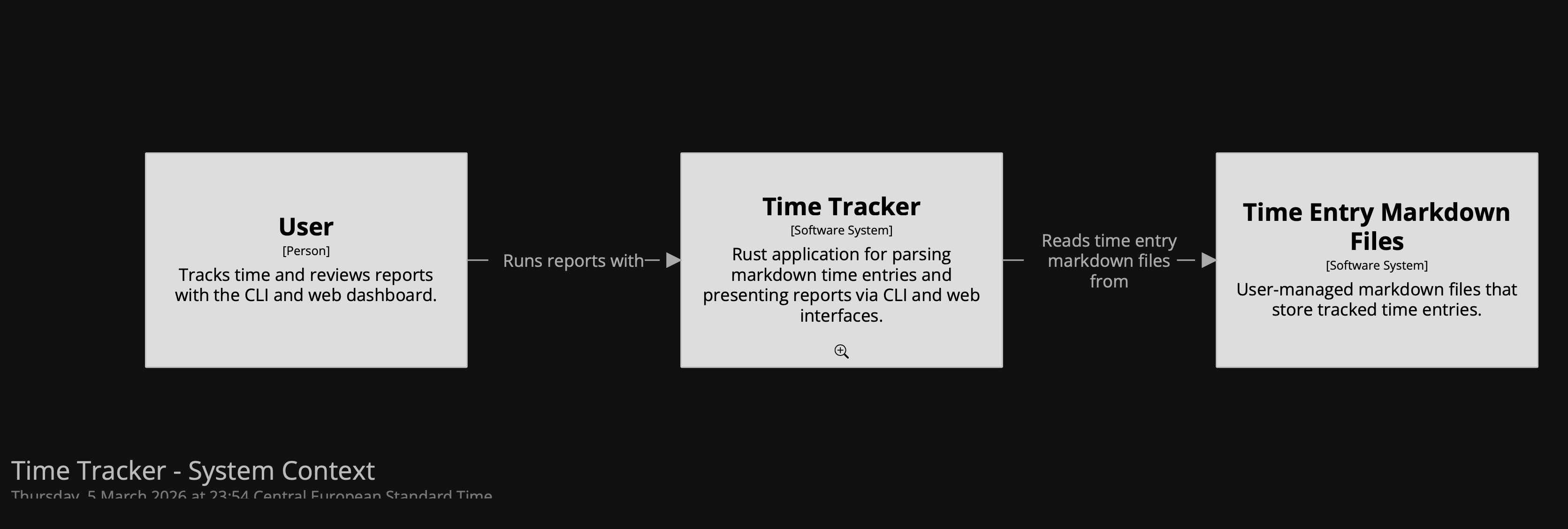
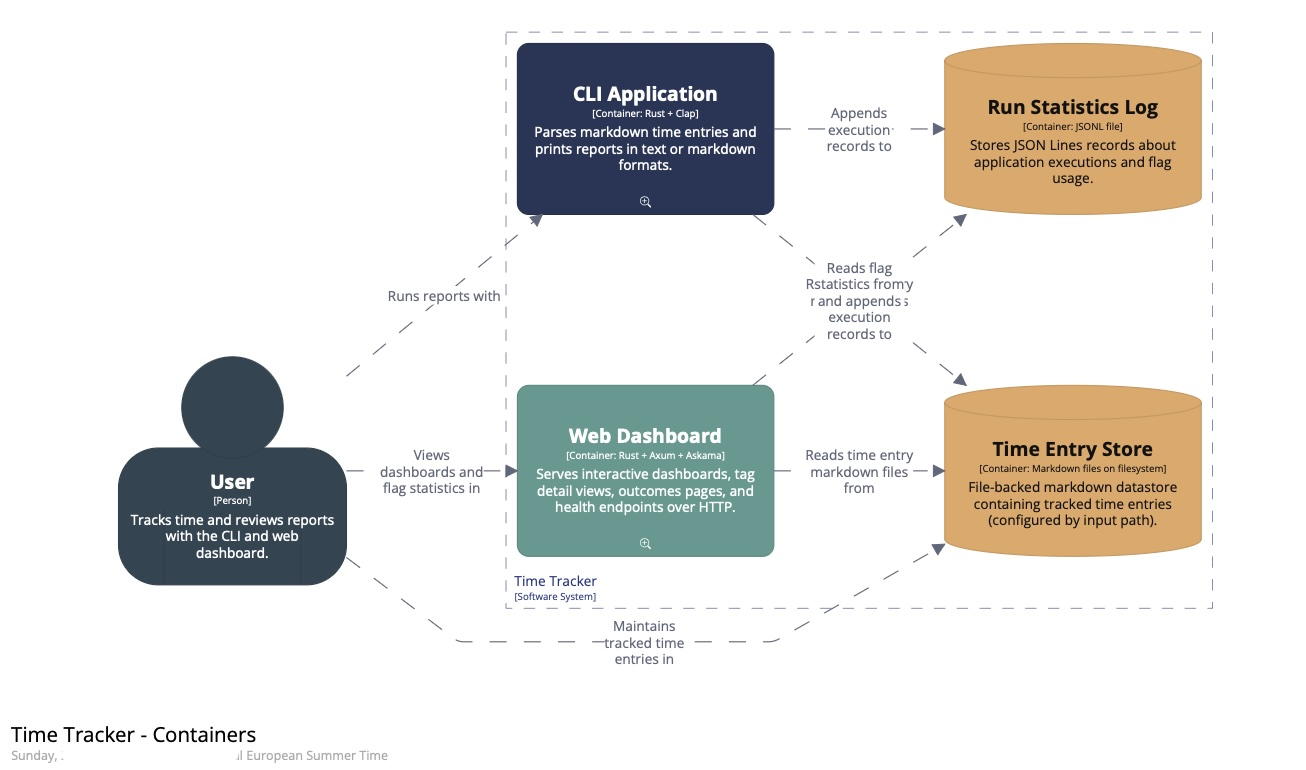
To start with, the agent inspected the Rust codebase to work out the system boundary. It established one Time Tracker software system with two runtime modes: a CLI and a web dashboard. Both use the same Markdown time-entry files.
(Apologies for the dark diagrams; dark mode was enabled when I took these screenshots. To enlarge them, open the images in a new tab.)
Here is a summary of the session:
- One of the first decisions was scope: whether to model only the web path or both runtime paths. The choice was to represent them as separate containers.
- We modelled a software system, two application containers, an internal datastore for run statistics, and the Markdown time-entry files as an external dependency. That first version was structurally correct.
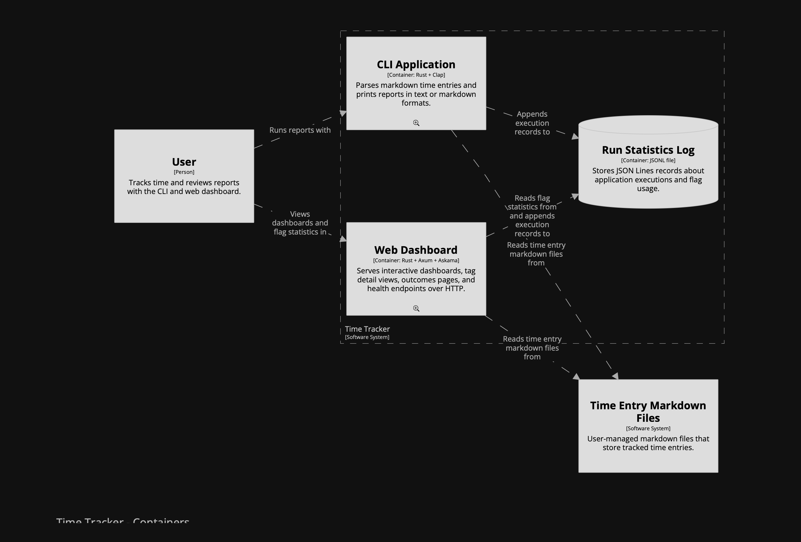
(I had completely forgotten about the runtime statistics feature ...)
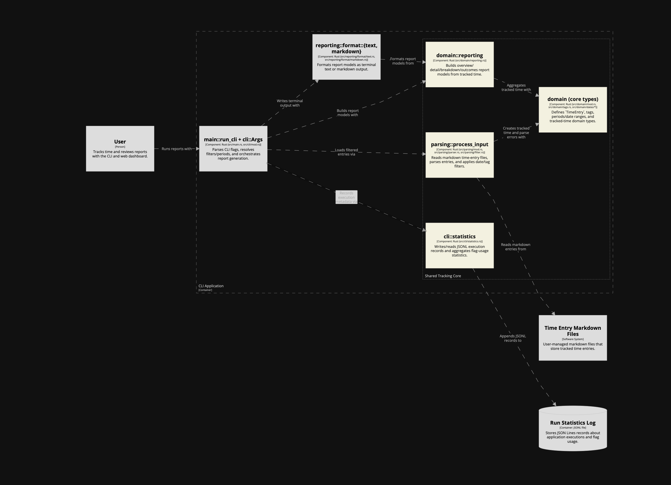
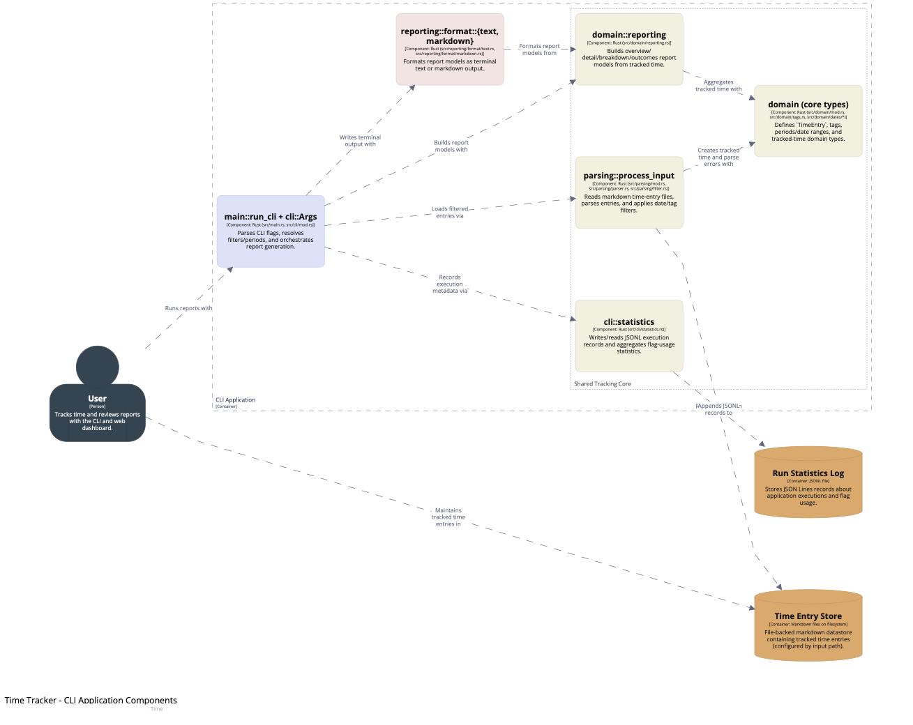
After the first version, something felt missing between the Markdown files and the CLI/web containers: the shared core logic. In C4 terms, that isn't another container; it belongs at component level. So I kept the container model strict and added the component level to make the shared logic explicit.
I initially asked it to model the shared core logic as a container, but the agent pushed back, and the model improved because of it. I asked it to add component views for both runtime containers instead of inventing a fake
corecontainer. That preserved a strict container model while making the architecture more insightful.Naming discussions helped sharpen the model. The agent came up with names I was not sure about, but on a first pass it probably did a better job than I would have. One direction I set explicitly was to name things as close as possible to the codebase. The names were not bad, but this is not where I want to leave room for interpretation.
To support those component views, we introduced a shared component fragment that both CLI and web could include. That shared layer covered parsing, domain types, reporting, and execution statistics. The result was a more accurate picture of how the code is actually organised.
- Once the model structure felt right, I shifted to presentation. I asked the agent to style it so different roles were easier to distinguish: CLI and web containers, shared components, adapters, renderers, and datastores. Then I asked for rounded boxes and a more explicit person-style user element.
The final result:
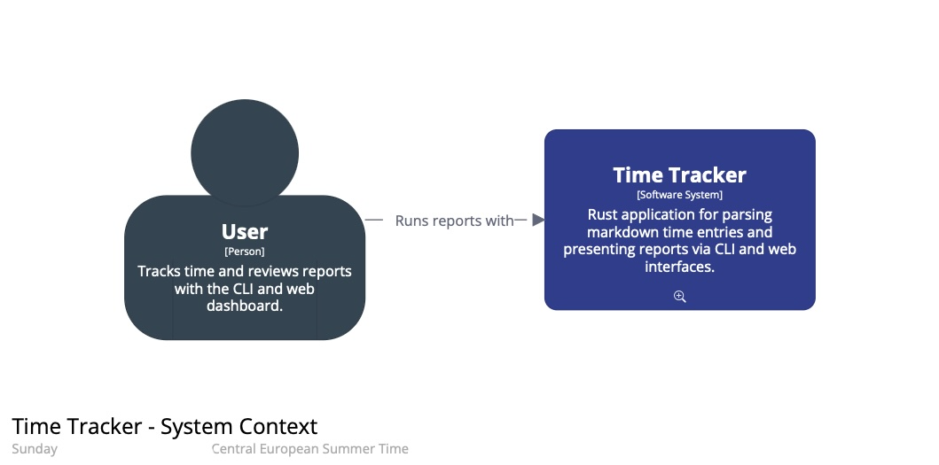
I have also made the generated static site with the diagrams available as it was straightforward to do with help from the agent. You can click the small magnifying glass icons to zoom into the next level.
In summary, this result took several passes: boundaries first; then the component layer; then names aligned with the code; and finally presentation.
The DSL in practice
One important artefact we have not discussed yet: the DSL itself. Here is the full model with the diagrams defined in the Structurizr DSL. All the edits were done by the agent, including the initial creation from scratch. I reviewed, asked questions, and iterated.
Before this, I typed every box and relationship by hand (scrolling up and down the file, or keeping two windows open), added tech stacks (taking care not to confuse the order of strings), and so on. Using the agent was a major documentation speed boost, and the DSL came out clean and organised the way I prefer: relationships after the element definitions, not inside them.
While I see the risk of not thinking things through, being relieved of painstaking manual element/relationship editing, working with agent also gave me:
- Iteration close to the code
- Meaningful discussions on abstraction levels and naming
- A knowledgeable architecture assistant at hand
Why I think it worked: the model is defined in text, so the agent can edit it like code. C4 provides guardrails through a small number of nested abstraction levels, and the DSL keeps names, descriptions, and styles consistent across views. A CLI tool to validate the model closes the loop, so the agent can check its work as it goes.
In addition, you can ask the LLM to review the model, in the context of the actual codebase or not.
Operationalising the workflow
Going forward, here is how I will instruct LLMs to work with C4 and keep the architecture diagrams up to date.
Agent Skill
First, after completing this experiment, I turned my learning into a reusable agent skill called modelling-c4-diagrams, which I can now use from any project.
AGENTS.md instructions
In the project's AGENTS.md I added a short reference so future agents can discover the DSL files and know how to validate/export. This avoids repeating the discovery work in each new session.
- **Architecture docs (C4)**: source DSL at `docs/c4/time-tracker.dsl` (shared components in `docs/c4/shared-tracking-core.dsl`); validate with `just architecture-docs-validate`; export static site with `just architecture-docs-export`
Verification
In this project, the LLM and I used the following commands to verify the output:
- Validate C4 Structurizr DSL:
structurizr-cli validate -workspace docs/c4/time-tracker.dsl
- Export C4 diagrams to docs/site for inspection (and GitHub Pages publishing)
structurizr-cli export -workspace docs/c4/time-tracker.dsl -format static -output docs/site
- View the architecture documentation
open docs/site/index.html
Structurizr interface to LLM
I found the validation loop with the CLI to work well. If the export succeeds, the DSL is valid and the views conform to the tool's rules.
That still does not tell you whether the model is accurate, or whether the diagrams communicate well. The C4 diagram review checklist is a good yardstick.
The LLM did not seem to require much extra instruction to create a proper model and views. I pointed it to c4model.com at the beginning of the session, and that may have been enough context. (Hard to tell what it knows or does under the hood.)
The skill I created and referenced above now serves as a main interface.
Conclusion
The architecture model and diagrams are insightful artefacts ("pictures can say more than words"). But most of the thinking and modelling usually happens visually, while recording it often becomes a chore. This experiment showed me that LLMs can help keep a model up to date without turning it into a separate manual process.
When the model is constrained (C4) and expressed as text (a DSL), you can version it like code, review it like code, and validate/export it through a CLI. Constrained text models plus validation give coding agents a better architecture-diagram workflow than free-form diagramming.
Addendum: Next experiments
Some follow-ups I might try if I run this workflow again.
Keeping the model in sync
Work with the LLM to design how to encode parts of the architecture model directly in the codebase. Use the C4 views as shared context, then define a way to keep the model in sync with the implementation. Unless you are using a very principled framework (maybe Spring in Java?), I expect this to be quite custom per project anyway.
Coding agents may lower the barrier to getting started with this kind of non-obvious quality-improvement work.
Verification beyond the CLI
Use an MCP like Chrome DevTools to inspect exported diagrams as a second verification step.
One concrete use case: manual editing is often required to position boxes and, especially, dependencies. A visual inspection could double-check that no text boxes overlap and that lines do not cross boxes.
Coding agents could be used to evaluate the shape of the architecture outside of the code.
Publishing and representation
Export to Mermaid (or PlantUML) for embedding in the agent's instructions, but keep the Structurizr DSL as the source of truth. Split the DSL so documentation for each container or component lives closer to the code.
A better LLM interface in tooling
This requires changes to Structurizr. It could provide build/run instructions for LLMs via an extensive --help output, or ship a dedicated subcommand that prints LLM instructions (similar to bd prime).